Showing posts with label cnc. Show all posts
Dremel tool CNC milling machine (in progress)
Cutting!
Finally, I was able to get the machine cutting! I'm quite glad it works, though there are some shortcomings. I was only able to engage each axis at a time- so i was only able to make linear cuts. ( the X was achieved by rotating the workpiece ) Each groove took about 20 runs back and forth, since the dremel tool wasn't powerful enough to make deep cuts in the plywood. Much more room for improvement and software development, but hey, it works!!
Electronics...
So begins the long task of wiring all the components together. I already tested each board and connection with an individual motor, but placing the wires unobtrusively which would reach around the board proved to be a different task. I ended up using over 24 feet of wire, of different kinds, to reach to all the motors and controllers.
I should note here, that I encountered a pretty serious problem. One of my Easy Drivers turned out to be defective, which was a nightmare since shipping a new one would take a week. To make a quick solution to the problem, I ended up wiring the two X axis motors to the same drivers, since they would have the same control anyways. A quick solution, but it ended up working!
Mounting the Dremel
Now for the most important part of the X gantry- the rotary tool. I spent a large amount of time thinking of ways to mount the dremel tool which would allow it to be removed easily, while retaining a firm grip on the tool, and not allowing movement. In the end, i found that two simple screws and a zip tie combined with a mount plate at the bottom sufficed!

Notice the rubber bands stretched on the Z axis. After more problems with stalling on the Z axis motor, I discovered a simple solution- to counteract the weight. The rubber bands work well in the working distance of the dremel tool, easing the load on the captive nut, allowing for smooth rotation of the motor. Simple, but effective!
Captive Nut Redesign
After a lot of testing with the Z axis, i encountered a large amount of problems with motor stalling, especially when the dremel tool was mounted. The problem was that the U-Screws weren't designed to take large amounts of load while maintaining low friction. So, i went to a new design, which was simply a metal enclosure for a nut. It works much better, and allows for much smoother vertical movement!
Z axis mounting
The mounting process for mounting the Y and Z axis onto the X gantry. Everything is starting to come together!
The Z axis in progress
The Z axis mounts on the Y axis, similarly to the way the Y gantry mounts on the X Gantry. Controlled by the same motor setup, it works in similar ways. This axis, the final one, gave me the most trouble, as the weight of the rotary tool put a lot more pressure on the motor. Note the change in coupling materials- i went through the familiar re-design process moving to machined aluminum, which worked much better.


To keep the Dremel mount plate from moving, i have it secured with two rollers, which stay rotation on either side. They run in C Channel grooves along each side of the mount plate.
Here is a detail of the Z axis system. Here you see for the first time the captive screw method I use for the majority of the machine- U-bolts made of spring steel, with a mounting hole drilled into one side. They have slightly more wobble than a regular captive nut, but have much more freedom, which works well with the imperfections in the threaded rod I bought!


To keep the Dremel mount plate from moving, i have it secured with two rollers, which stay rotation on either side. They run in C Channel grooves along each side of the mount plate.
Here is a detail of the Z axis system. Here you see for the first time the captive screw method I use for the majority of the machine- U-bolts made of spring steel, with a mounting hole drilled into one side. They have slightly more wobble than a regular captive nut, but have much more freedom, which works well with the imperfections in the threaded rod I bought!
Re Designed Bearings
After Experiencing a good amount of wobble on the X axis, i decided to remedy the problem by adding more constraints to the bearings. Since the wobble was along the Z axis, I needed to add horizontal bearings. Since the movement would be fairly slow anyways, simple low friction pads worked fine. They are on a variable distance, which is set with a screw!
The Y Gantry!
Bearings
After doing some research, I found that a V shaped bearing system works much better than just the horizontal and vertical bearings I used on the X axis. So, for the Y axis, I used aluminum L-bar for both the track and the bearing mount, with quite satisfying results.
Right- A Finished bearing mount.
Bottom- The mounts in place on the rails.
Mounting The Gantry
With the bearings mounted onto L brackets, I simply attached them to a flat piece of wood, which will later hold the Z-axis. The bearings are tightened by a series of screws holding them in place. To prevent jitter, I drilled another hole for a screw, but instead, my drill bit got stuck in the hole, and holds the two pieces together quite well!
Motor Controller!
After frustrations getting the Arduino to power my stepper motors directly (which was a big mistake), i decided to buy an Easy Driver to test out my motors while I was still building the gantries. It works incredibly well, and is very easy to set up! What you see here is an stand alone board that rotates the motor continuously, and can plug into an outlet, perfect for testing!
Couplings....
I think I've hit a major snag in building this machine, even after taking the gear grafted on the motors, its extremely difficult to attach this shaft to the linear screw. I tried making a coupling out of wood, but it was too soft and too loose: the coupling achieved was atrocious! I went back and remade the coupling out of aluminum.
The new coupling attaches to the shaft with two screws... (maybe i'll have to move to 3 screws if the wobbling persists). A coupling is made, but unfortunately, the hole i drilled for the motor shaft is a fraction of a millimeter too large, so the shaft wobbles, and sometimes gets off enough to stall the stepper motor.... Perhaps another solution will be nessessary..! i'll be mounting this motor on the actual CNC next, should be exciting!
Motors!
I won a nice set of stepper motors, previously used in a Maker-bot on eBay! These are NEMA-17, with a holding torque of 1.7 n-m. Its small, but hopefully they will be strong enough to push the chassis. They are a pain to control, right now i'm plugging them directly to an Arduino, which doesn't seem to have too much power.... i think the next step will be to build a controller for them.
Here is one of the motors mounted directly onto the bearing housings. One of the most annoying thing about these motors is the little black gear grafted on the shaft: i tried everything, heating it, pulling it, hitting it, but it wouldn't budge. I ended up breaking the edge off with a hammer, and then using an improvised gear pull to extract them.... The amount of force used bent a piece of 4mm steel like a ribbon. These motors are a pain!!
Bearing housings finished!
The bearing housings are done! Here is a dry test of what the assembly will look like. At the moment, only the near aluminum channel is secured, so i can work on the chassis separately.
Bearing Housings...


I needed housings for the bearings that would support the screws (that drive the chassis back and forth). Without a big enough drill bit, however, i had to improvise to make holes big enough to accomodate the bearings. To the right is my Dremel hole cutter, which was painstakingly laborious. Its a messy job, but the housings hold the bearings just fine!
The Y chassis framework
Stopped by Ace's today to pick up some parts for the machine. The best option i found for a linear bearing system was to use sliding door rollers and aluminum C channel. Here are the door rollers screwed into the sides of the Y chassis.
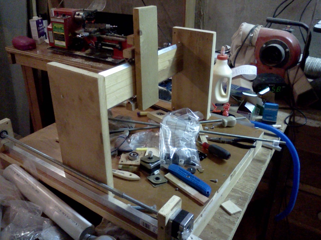
Here is the completed Y chassis framework: I'm still not sure how exactly I'll mount the Z chassis, but the general shape is there, and the chassis moves fairly well in the aluminum channels. It rolls very well even under large weight, so I think it'll do fine. The rollers aren't perfectly perpendicular, but the linear screws on either side should suffice to keep the chassis steady.
A closeup of the window roller in its C channel housing.
Here is the completed Y chassis framework: I'm still not sure how exactly I'll mount the Z chassis, but the general shape is there, and the chassis moves fairly well in the aluminum channels. It rolls very well even under large weight, so I think it'll do fine. The rollers aren't perfectly perpendicular, but the linear screws on either side should suffice to keep the chassis steady.A closeup of the window roller in its C channel housing.
Making the Cutting bed


The cutting bed of a milling machine has to be as flat and horizontal as possible. Unable to aqquire enough aluminum, i decided to build the base out of wood, which turned out to be a more complicated task than at first sight. I straightened out two flat planks, and screwed on two odd pieces of wood on the bottom, varying the heights of each screw to achieve the flattest surface. A piece of plywood on top gives extra smoothness!
Subscribe to:
Posts (Atom)


